

CAPSTONE DESIGN SHOWCASE 2022
-
DAYS
-
HOURS
-
MINUTES
-
SECONDS
COMING SOON


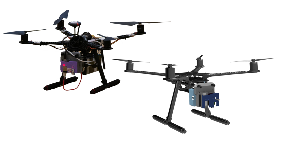
Team members
Ha Tze Han Shaun (EPD), Leong Yu Siang (EPD), Lim Jin Feng, Nick (EPD), Hank Ng Zhi Heng (ESD), Wang Zixuan (ISTD), Tan Jianhui (ISTD)
Instructors:
Cyrille Pierre Joseph Jegourel, Ying Xu, Kwan Wei Lek
Writing Instructors:
Teaching Assistant:


 Ha Tze Han Shaun
Engineering Product Development
Ha Tze Han Shaun
Engineering Product Development
 Leong Yu Siang
Engineering Product Development
Leong Yu Siang
Engineering Product Development
 Lim Jin Feng, Nick
Engineering Product Development
Lim Jin Feng, Nick
Engineering Product Development
 Hank Ng Zhi Heng
Engineering Systems and Design
Hank Ng Zhi Heng
Engineering Systems and Design
 Wang Zixuan
Information Systems Technology and Design
Wang Zixuan
Information Systems Technology and Design
 Tan Jianhui
Information Systems Technology and Design
Tan Jianhui
Information Systems Technology and Design
Ha Tze Han Shaun
Engineering Product Development
Leong Yu Siang
Engineering Product Development
Lim Jin Feng, Nick
Engineering Product Development
Hank Ng Zhi Heng
Engineering Systems and Design
Wang Zixuan
Information Systems Technology and Design
Tan Jianhui
Information Systems Technology and Design


